Which Working Area entries distinguish VIT-F models?
VIT-F35, VIT-F52 and VIT-F85 list 12000*350mm, 12000*520mm and 12000*850mm respectively, under the original Working Area label.

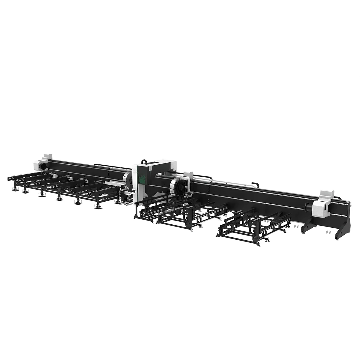
Tube Laser Cutting Machine
VIT-F Laser Cutting Machine configuration brings the workpiece brief and the installation discussion together. The published range lists VIT-F35, VIT-F52 and VIT-F85, with 12-20kw laser power, Max/IPG source alternatives and FSCUT control. Each model has its own Working Area entry, which should retain that label during selection.
For a project involving long stock, describe the incoming material and the proposed handling route early. A workpiece length, a machine dimension and a complete installation arrangement are different pieces of information. Keeping them separate gives the supplier a clear set of questions about the equipment and the space around it.
Choose an individual model below to view its complete technical specification. The series overview shows selected parameters for comparison.
Working Area is listed as 12000*350mm for VIT-F35, 12000*520mm for VIT-F52 and 12000*850mm for VIT-F85. Use those exact model-field pairs in the comparison. The second dimension should not be relabeled as a confirmed maximum tube diameter without a specific response about the proposed section and arrangement.
The shared motion fields are Max Moving Speed of 100m/min and Max Acceleration of 0.6-1.2G. Positioning Accuracy is ±0.05mm and Repositioning Accuracy is ±0.02mm. These describe published machine specifications; they do not establish material cutting speed, a finished-part cycle or guaranteed dimensions on an unspecified component.
The source row names Max/IPG as laser source alternatives and FSCUT as the control system. Here Max is a source name, not the word maximum. A quotation should identify the actual source and selected power within the published range, preserving the distinction between available choices and the equipment being offered.
Prepare VIT-F workpiece requirements with section drawings, material grades, wall dimensions, incoming lengths and individual workpiece masses. Show the end features and any holes or slots required on the finished part. Identify critical dimensions and the current drawing revision, treating these as application requirements to be discussed rather than proven machine results.
For the proposed stock route, describe where material arrives, how it is intended to approach the equipment and where finished pieces must go. If existing lifting or support equipment is involved, identify it in the brief. Ask which arrangements are part of the proposed supply and which need separate planning or confirmation.
Machine Size is published as 11800*2280*2600mm, while Product Weight is given as 5000-20000kg. Keep the weight range associated with the product; it is not a workpiece-load capacity. Request dimensions and weight for the actual configuration, plus an installation drawing, before treating the general table as a completed layout.
The Voltage row lists 220V 1P 50HZ /380V 3P 50HZ. Provide the intended destination supply and ask which electrical configuration is offered. The two entries should not become a claim that one unspecified machine accepts every listed supply without configuration or a written equipment response.
Combine the selected model, power, source and control with the latest section drawings and site information in the quotation request. Keep Working Area, Machine Size, product weight and handling questions in distinct fields. This makes unresolved items visible and lets later equipment revisions be compared against the same documented workpiece and installation requirements.
VIT-F35, VIT-F52 and VIT-F85 list 12000*350mm, 12000*520mm and 12000*850mm respectively, under the original Working Area label.
The published 100m/min field is Max Moving Speed. Cutting-time questions need the material, drawing and chosen configuration.
No. The 5000-20000kg range is labeled Product Weight. Ask separately about the proposed workpiece and handling arrangement.
The table lists machine dimensions. Request the installation drawing and handling scope needed for your proposed layout rather than assuming a complete working area around the equipment.
Provide the destination supply and ask the offer to identify its electrical configuration against the two published Voltage entries.
Share your material, dimensions and process. Start a conversation about the right configuration.